Before explaining how the limited-slip action works, let's look at how the differential part works.
When you go around a corner, the inside wheels have less ground to cover than the outside wheels, so naturally, they spin more slowly. The differential's job is simply to allow the two drive wheels to turn at different speeds while still staying mechanically connected to the gearbox.
When the car is going straight, the differential itself spins at the same speed as the wheels, and from your point of view as an honorary differential, all the gears inside are stationary. When the car goes around a corner and one wheel has to go faster than the other, all you'd see, as a differential, is the two axles turning in opposite directions.
Now look at the diagram of the Quaife differential and imagine the sun gear in front (the gears attached to the axles are called sun gears) turning clockwise. The pinion gears around the outside of the sun gear therefore turn counterclockwise. The pinion gears from one side of the differential mesh with pinion gears from the other side, so they turn clockwise, and those pinion gears turn the sun gear on the far side counterclockwise. That, if you've lost track, means it's turning in the opposite direction from the sun gear in front, which is just what you, as a differential, want to see when you're going around a corner.
Coasting around that corner, there's no load transmitted through any of these gears, but hit the throttle and things get complicated. Look closely at what happens when the differential tries to drive the wheels. Assuming the car is going straight and there's equal grip on both wheels, the differential housing turns, which forces the pinion gears, trapped in little pockets around the perimeter of the diff, to move with it. These pinion gears are meshed with the sun gears, and because none of the gears are turning (relative to the diff housing, that is), the sun gears have to follow along, spinning at the same speed as the differential.
The gear teeth can only push on each other with a force directly perpendicular to the face of the tooth, so if the tooth is angled, so is the force on the gear teeth.
Now, the pinion gears don't rotate on a shaft; instead, they sit in tight-fitting pockets, with the tips of their gear teeth rubbing on the inner walls of each pocket. When the differential housing turns and the pinion gears push on the sun gears, the pinion gears get shoved back against the walls of their pockets. Of course, the more torque that gets applied, the harder they get shoved against the wall.
That's going to be very important in a second.
When one wheel loses grip and tries to spin, all the gears have to start turning, just as they did when we were coasting around a corner, but now that the pinion gears are being shoved against the walls of their pockets, there's some resistance. This is just the beginning of the resistance, though. In the middle, where the pinion gears mesh and the pinion on the gripping side tries to turn the pinion on the slipping side, something interesting happens.
The pinion gears are cut with helical gear teeth that mesh at an angle. When these angled teeth push against each other, the angle of the teeth causes them to pull each other up against the end of their pockets.
The combined friction of the tip of the pinion gear teeth rubbing against the pocket walls and the ends of the pinions rubbing against the ends of the pockets actually creates enough resistance to prevent the inside tire from spinning.
When designing a new application, engineers can adjust the amount of resistance in the diff by changing the shape of the gear teeth and the angle of the helical pinion gears. To see how this works, just look closely at the interface between two gear teeth, starting with gear tooth No. 1 on the left. The bottom tooth is pushing up with a force represented by the little green arrow. At the gear tooth interface, the bottom tooth pushes up on the top tooth with that same force (but now the arrow is white), and if there's enough resistance on the other gear, the top tooth will push back with the same force.
The gear teeth can only push on each other with a force directly perpendicular to the face of the tooth, so if the tooth is angled, so is the force on the gear teeth (the white arrow). In gear tooth No. 2, you can see the white arrow is now angled. This same force can be looked at as two forces, one pushing up (green), and one pushing to the side (red). As the angle of the teeth gets steeper, as in gear tooth No. 3, the amount of force pushing to the side increases. The force shoving the pinion gears into the pocket wall comes, in part, from these little red arrows.
The majority of the resistance and virtually all of the tuning happens when the angle of the helical pinion gear teeth is changed. A steeper helix translates directly into bigger red arrows shoving the pinion gears into the end of the pockets. If there's no resistance from the gear on top, the gears will simply turn and there won't be any red arrows at all. No red arrows mean no limited slip, so if one wheel is completely off the ground, the diff will act as an open differential.
Showing posts with label Faq. Show all posts
Thursday, 3 October 2013
Tuesday, 19 March 2013
Machiavelli Test
A very entertaining personality test which determines whether or not you have faith in humanity.
Take the test HERE
As for me...
"Your score was 51 of 100.
This puts you in the category of the low Machs, people who will hold out for the goodness of the world and avoid manipulation. Not the people Machiavelli would approve of.
A graph of how others who have taken this have scores is below. These scores should not be taken as population norms though, the people who seek out tests of machivellianism on the internet are most likely not representative."
Now what exactly is Machiavellianism, and where did it originate from?
Post your results in the comment section below.
Take the test HERE
As for me...
"Your score was 51 of 100.
This puts you in the category of the low Machs, people who will hold out for the goodness of the world and avoid manipulation. Not the people Machiavelli would approve of.
A graph of how others who have taken this have scores is below. These scores should not be taken as population norms though, the people who seek out tests of machivellianism on the internet are most likely not representative."
Now what exactly is Machiavellianism, and where did it originate from?
Machiavellianism
It is "the employment of cunning and duplicity in statecraft of in general conduct", deriving from the Italian Renaissance diplomat and writer Niccolò Machiavelli, who wrote II Principe (The Prince) and other works. The word has a similar use in modern psychology where it describes one of the dark triad personalities, characterised by a duplicitous interpersonal style associated with cynical beliefs and pragmatic morality. "Machiavellian" (and variants) as a word became very popular in the late 16th century in English, though "Machiavellianism" itself is first cited by the Oxford English Dictionary from 1626.
| Niccolò Machiavelli |
Machiavellianism is also a term that some social and personality psychologists use to describe a person's tendency to be unemotional, and therefore able to detach themself from conventional morality and hence to deceive and manipulate others. In the 1960's, Richard Christie and Florence L. Geis developed a test for measuring a person's level of Machiavellianism. Their Mach - IV test, a twenty-statement personality survery, became the standard self-assessment tool of Machiavellianism. People scoring high on the scale (high Machs) tend to endorse statements such as "Never tell anyone the real reason you did something unless it is useful to do so," but not ones like, "Most people are basically good and kind". Using their scale, Christie and Geis conducted multiple experimental tests that showed that the interpersonal strategies and behaviour of "High Machs" and "Low Machs" differ. Their basic results have been widely replicated. Measured on the Mach - IV scale, males are, on average, slightly more Machiavellian than females.
Post your results in the comment section below.
Monday, 18 March 2013
Crankcase Ventilation Valve (CCV) + DIY Replacement
The CCV takes oily crankcase gases (found in all internal combustion engines), separates the oil, returns the oil down the dipstick tube to the sump, and recycles the gases into the intake to be combusted.
If your daily commute is relatively short, and the engine rarely gets up to full operating temp, you need to worry. Solution: take it for a hot highway drive for about 30 minutes every week or two.
If your daily commute is not short, and the engine gets up to full temp every time you drive, you have no need to worry... for now.
If your daily commute is relatively short, and the engine rarely gets up to full operating temp, you need to worry. Solution: take it for a hot highway drive for about 30 minutes every week or two.
If your daily commute is not short, and the engine gets up to full temp every time you drive, you have no need to worry... for now.
| 1. Pressure Regulating Valve 2. Vent Pipe 3. Connecting Line 4. Vent Hose 5. Bolt 6. Vacuum Hose 7. Return Pipe 8. Dipstick O-ring |
Determining If Needing Replacement
1) Cracks in the air hoses leading to and from the CCV.
Symptoms: lean condition, P0171 and P0174.
Diagnosis: Remove oil filler cap while at idle. Leaking CCV system will cause stumbling and a very strong suction on the oil filler cap.
2) Failure to separate oil from vapour
Symptoms: More-than-expected oil consumption - oily crankcase gases are being returned to the intake instead of separated properly.
Diagnosis: Check plugs and DISA for oil contamination.
3) Clogged with oil-ice or sludge
Symptoms: 'splosions in the engine bay
Cause: Short trips in cold weather, allowing moisture (inherent to gasoline combustion) to get in the oil and never burn off. Moisture mixes with oil and makes yellow snot. Yellow snot sticks in CCV, car is left outside in freezing temperature, snot turns to ice-snot, then the crankcase vapours that the CCV is supposed to separate instead just build pressure inside the crankcase... until POW!
Early Diagnosis: yellow goo or black sludge under the valve cover or on the underside of the filler cap
Late diagnosis: oil all over the place, terrible lean conditions, maybe oil fills the cylinders, wallet vanishes.
DIY Replacement
E46 On Board Computer (OBC) Hidden Functions
Instructions to access hidden OBC functions: Make sure doors are closed.
1. Hold Trip Reset while turning ignition key to on position
2. OBC should show "Test"
3. Use Trip Reset to select function 19.0 that unlocks all the features
3. Wait for display to show "Off"
4. Depress Trip Reset for 1/4 second and release it
5. With no delay press Trip Reset several times to select one of the following function s
==========================================
BMW E46 On-Board Computer (OBC) Hidden Codes
nr example description
1 Car Engine and cluster data
1.0 46nnn Chassis nr/VIN serial number (last 5 digits)
1.1 4nnn K-number
1.2 690236 Cluster Part #
1.3 045210 Coding (04)/diagnosis (52)/bus index (10)
1.4 1200 Week (12)/year of manufacture (2000)
1.5 09_160 Hardware (09) and software # (16.0) of cluster
1.6 Not used
1.7 04__44 CAN-version (04) KI-revision index (44)
2 (test) Cluster System Test - Activates the gauge drivers,
indicators and LEDs to confirm function
3 SI Data
3.0 1098 Used fuel in liters since last SI (Service Inspection)
3.1 0231 Periodic inspection days; elapsed days (since last SI)
4 Momentary Consumption
4.0 0145+ Instant fuel consumption - 0145=14.5 liters/100km
4.1 0018 Instant fuel consumption - 0018=1.8 l/Hour
5 Distance Gone Consumption
5.0 082 Average mileage; 082=8.2 liters/100km
5.1 0536 Calc. km to refuel (momentary distance to go)
6 Fuel Level sensor inputs in liters
6.0 109330+ Fuel level averaged; Left half sensor input=10.9 liters; Right sensor input=33.0 liters
6.1 0439+ Total tank level averaged; vlgs 6.0: 10.9+33.0=43.9 liters
6.2 0442+ Indicated value (44.2) and tank phase
7 Temperature and Speed
7.0 021+ Coolant/Engine temperature (2.1C)
7.1 130 Ambient/Outside temperature - chg met 5 pts. 125/130/135
7.2 + Engine speed / Current RPMs 1/min
7.3 + Vehicle speed / Current Speed in km/hour
8 Input value in HEX form
8.0 1d0+ System voltage ADC-Value Hex code
8.1 26C33C+ ADC Values HG left/HG right
8.2 0000 ADC Value brake degradation sensor (000=o.k.)
8.3 18C ADC Value outside temperature
9 Battery
9.0 140 Battery Voltage - 140 = UB 14.0v
9.1 242013+?
9.2 074_78+?
9.3 0011+?
10 Not used
11 Not used
12 Not used
13 GonG Gong Test
14 Not used
15 Status cluster I/O-ports (bit codes) 0=low; 1=high
1st-belt contact, seat belt fastened=0; 2) ignition lock contact, key inserted=0; 3) door contact, door open=0; 4) clock button pressed=0; 5) SI reset=0, for reset=0; 6) EGS transmission failure=0
Status Digital Outputs (bits) 0=inactive, 1=active
1) Gong output; 2) Brake warning lamp; 3) Low fuel warning lamp; 4) EGA lamp; 5) seat belt lamp; 6) manipulation dot
16 Not used
17 Not used
18 Not used
19 Lock Status; unlocks functions in range 3-18
19.0 L-On/L-Off Unlock: press button when "L-Off"
20 Not used
21 Software Reset; reset OBC settings
00 End of test
1. Hold Trip Reset while turning ignition key to on position
2. OBC should show "Test"
3. Use Trip Reset to select function 19.0 that unlocks all the features
3. Wait for display to show "Off"
4. Depress Trip Reset for 1/4 second and release it
5. With no delay press Trip Reset several times to select one of the following function s
==========================================
BMW E46 On-Board Computer (OBC) Hidden Codes
nr example description
1 Car Engine and cluster data
1.0 46nnn Chassis nr/VIN serial number (last 5 digits)
1.1 4nnn K-number
1.2 690236 Cluster Part #
1.3 045210 Coding (04)/diagnosis (52)/bus index (10)
1.4 1200 Week (12)/year of manufacture (2000)
1.5 09_160 Hardware (09) and software # (16.0) of cluster
1.6 Not used
1.7 04__44 CAN-version (04) KI-revision index (44)
2 (test) Cluster System Test - Activates the gauge drivers,
indicators and LEDs to confirm function
3 SI Data
3.0 1098 Used fuel in liters since last SI (Service Inspection)
3.1 0231 Periodic inspection days; elapsed days (since last SI)
4 Momentary Consumption
4.0 0145+ Instant fuel consumption - 0145=14.5 liters/100km
4.1 0018 Instant fuel consumption - 0018=1.8 l/Hour
5 Distance Gone Consumption
5.0 082 Average mileage; 082=8.2 liters/100km
5.1 0536 Calc. km to refuel (momentary distance to go)
6 Fuel Level sensor inputs in liters
6.0 109330+ Fuel level averaged; Left half sensor input=10.9 liters; Right sensor input=33.0 liters
6.1 0439+ Total tank level averaged; vlgs 6.0: 10.9+33.0=43.9 liters
6.2 0442+ Indicated value (44.2) and tank phase
7 Temperature and Speed
7.0 021+ Coolant/Engine temperature (2.1C)
7.1 130 Ambient/Outside temperature - chg met 5 pts. 125/130/135
7.2 + Engine speed / Current RPMs 1/min
7.3 + Vehicle speed / Current Speed in km/hour
8 Input value in HEX form
8.0 1d0+ System voltage ADC-Value Hex code
8.1 26C33C+ ADC Values HG left/HG right
8.2 0000 ADC Value brake degradation sensor (000=o.k.)
8.3 18C ADC Value outside temperature
9 Battery
9.0 140 Battery Voltage - 140 = UB 14.0v
9.1 242013+?
9.2 074_78+?
9.3 0011+?
10 Not used
11 Not used
12 Not used
13 GonG Gong Test
14 Not used
15 Status cluster I/O-ports (bit codes) 0=low; 1=high
1st-belt contact, seat belt fastened=0; 2) ignition lock contact, key inserted=0; 3) door contact, door open=0; 4) clock button pressed=0; 5) SI reset=0, for reset=0; 6) EGS transmission failure=0
Status Digital Outputs (bits) 0=inactive, 1=active
1) Gong output; 2) Brake warning lamp; 3) Low fuel warning lamp; 4) EGA lamp; 5) seat belt lamp; 6) manipulation dot
16 Not used
17 Not used
18 Not used
19 Lock Status; unlocks functions in range 3-18
19.0 L-On/L-Off Unlock: press button when "L-Off"
20 Not used
21 Software Reset; reset OBC settings
00 End of test
Sunday, 17 March 2013
DIY: M54 Cooling System Refresh
Difficulty: ** (out of 5 stars)
Time: 6.5 Hours
Tools: Phillips Screwdriver, Jack, Jack Stands, 13mm Socket, 3 long extensions, Universal Elbow Attachment, Ratchet, 5/8" Socket, Allen Head Socket, Torx T-30, Flashlight, Rubber Mallet, Torque Wrench.
*Note - Every 60,000 miles : water pump + thermostat should be replaced. Every 90,000 miles : Radiator, Expansion Tank, Fan Clutch and Plastic Cooling Fan
Credits to : pimpin325ci via Bimmerforums.com
***REMEMBER to make or distinguish in some way ALL of the parts, bolts, nuts, and clips that you remove for easy re-installation with zero problems. Also make note of every sensor plug and whatever else that you unplug or remove so that you remember to put them back during re-installation.***
The car is a 2001 325Ci. The parts used are: ECS Tunning Level II Cooling System Refresh.
Parts Purchased:
Directions:
Time: 6.5 Hours
Tools: Phillips Screwdriver, Jack, Jack Stands, 13mm Socket, 3 long extensions, Universal Elbow Attachment, Ratchet, 5/8" Socket, Allen Head Socket, Torx T-30, Flashlight, Rubber Mallet, Torque Wrench.
*Note - Every 60,000 miles : water pump + thermostat should be replaced. Every 90,000 miles : Radiator, Expansion Tank, Fan Clutch and Plastic Cooling Fan
Credits to : pimpin325ci via Bimmerforums.com
***REMEMBER to make or distinguish in some way ALL of the parts, bolts, nuts, and clips that you remove for easy re-installation with zero problems. Also make note of every sensor plug and whatever else that you unplug or remove so that you remember to put them back during re-installation.***
The car is a 2001 325Ci. The parts used are: ECS Tunning Level II Cooling System Refresh.
Parts Purchased:
Steps (out of 26)
1. First jack up the car on the front, both sides, so that you have access all around, above and below the car. Use stands of course.
![]() |
| Right hand drive. |
2. Remove the splash guard with a Phillips screwdriver, there are 7 screws, which stay attached to the splash guard.
3. Next take a bucket or pan (use something with a holding capacity of about 5 gallons) and place them under the radiator and expansion tank drain plugs. They are blue circle plugs with a large phillips head. You can use just about anything that will fit in there to un-screw them, but be careful not to damage them as they are plastic. The radiator drain plug you will replace because a new one comes in the kit. The expansion tank drain plug however, you will reuse, it also STAYS in the housing, so do not try to remove it.
4. After those have drained out, move to the engine block drain plug. It is between the two exhaust manifolds up in a pretty easy to access area on the passenger side of the engine. It is easy to see and easily recognizable. You will need a 13mm socket a couple (2 or 3) long extensions and a universal (bendy elbow attachment) in order to get to it with your ratchet. Unscrew this and take it completely out, with your bucket ready to catch the coolant. (coolant will shoot out and hit everything in its path on an angle, so use protection for eyes and mouth).
5. The first thing you will need to take off is your air intake. Disconnect the Mass Air Flow sensor and remove that as well.
6. Remove the air duct that is above your kidney grills. It takes 3 pins that you pry up on the center part and then pry up the while pin clip.
7. Fan removal. Unplug the two electrical connectors on the passenger side of it, pop out the pin clip on the right side, and remove the Torx T-25 screw. After this, simply lift it out.
Once you have the fan out, you will have a lot more room to work in so that you can start removing parts. It doesn't matter which order you remove some of the parts in (unless things obviously have to be removed before you can get to others).
8. Take off your belts. There is a hydraulic tensioner on the main belts and a mechanical one on the A/C belt. For the hydraulic tensioner you use a Torx T-50 bit, put it on the centre bolt of the pulley on the tensioner (after you pop off the dust cap) and turn it CLOCKWISE. Use a breaker bar. This will depress the tensioner, then pull the belt off the pulley. Take out your wrench and pull the belt out.
If you have a mechanical tensioner for this main belt, you just use a 5/8" socket and put it on the "nut shaped" part of the tensioner and turn it away from the belt to release tension.
For the A/C belt, use the 5/8" socket and turn it away from the belt to release the tension. Remove both of the belts.
Remove all the hoses at once. NOTICE if the hose attachments are hard to get off. Spray WD-40 around the fitment and let it soak to loosen it up. Be careful not to damage the plastic attachments that the hoses attach to. Also, the hoses will still have some coolant left in them that will drain out when you remove them.
9. On the upper radiator hose, pull up on the easy release clips, two on the expansion tank side and one on the thermostat side. Don't worry about saving the older bleeder plug because the new hose will have a new one too. Pull the hose out.
10. Remove lower radiator hose. Unplug the sensor attachment from the top of it. This goes to the "fan switch" inside the lower radiator hose, don't worry about saving that either because the kit comes with a new one. Pull up the easy to release clips on both ends of the hose and pull that hose out.
11. Remove the two hoses attached to the expansion tank.
The upper one goes clear to the back behind the engine to the heater core behind the fire wall. You will need to remove your cabin air filter tray to this.
11a. First turn 90 degrees clockwise the three white spring loaded clips. Remove that cover and then your filter.
Take a Torx T-30 (or Allen Head Socket) bit and remove the four screws securing the tray. Pull that up and out. For even more hand room, you may want to remove the back wall behind that. Remove the two other (one per side) Torx screws on the wall and pull that up and out.
You should be able to see two hoses attach into this back wall. The one with the blue ring around it is the one you are going to remove. Take a flat head screw driver and unscrew the clamp, pry this hose off. Pop up the clip on the attachment on the opposite end attached to the expansion tank and pull that off. Pull the hose out.
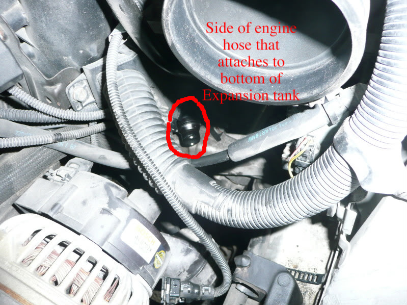
12. Remove the lower expansion tank hose. This hose is short and attaches to the right side of the engine. Pop up the clips on both ends and pull the hose out. You will most likely need to get back under the car to get it off of the expansion tank because it is on the bottom.
13. The next hose is kind of a pain in the ass. The front of it is just an open ended hose with a clamp over it to secure it to the "water inlet valve". Just unscrew this a bit and pull it off. Use a flash light and follow the hose back with your hand, reaching around. It goes all the way back and around to the back of the engine. You may want to remove the right plastic engine cover (the ones with the white groves) because this gives you a little peep hole to see down to the opposite end of this hose. Once you have found it, you can attempt to pop up the pin to remove it. However, ( if you can not get any sort of screw driver back in that area, feed a wire down through the peep area and hooked it around the wire clip. Then pulled up.)
Finally, once you have gotten these 5 hoses off, you can remove the thermostat and water pump.
14. Start with the thermostat because it is above the water pump. Unplug the sensor attachment clip from the top of the thermostat. Remove the four bolts (3x 10mm and 1x 13mm). Pull off the thermostat, you have to turn the right side downwards because there is a metal arm that kind of holds it in.
15. Remove the water pump pulley. There are 4x 10mm bolts attaching it on. Have someone help you by holding the pulley still, because it will turn when you try to take out the bolts. This shouldn't be hard because the bolts are not torqued on tight at all. Once the four bolts are out, pull off the pulley.
16. Take out the water pump. Remove the 4x 10mm bolts. The pump will most likely be stuck on, so screw in two (one on each side) M6 (6 mm metric bolts) 25 mm in length (about), into the two side holes on the pump (they are the two that you didn't take any of the bolts out before). You want to thread these bolts in until they make contact with the engine block, once they do, continue screwing them in EVENLY. This will pry the water pump out of the engine block.
17. OK the dreadful Expansion Tank. Unplug the coolant level sensor plug. You can remove that if you want but there is a new one in the kit. Everything should now be disconnected from the tank so, if you're lucky, get about it and grasp it from underneath or however you can handle and pull it up. (if this does not work, have someone beat if from the bottom with a hammer while you pull it upwards).
Now you've got everything removed. This is sort of the mid-way point of the job. You've already gotten basically ALL of the HARD work done and the rest will got 2324352428432 times faster. Take a lunch break.
18. Flush out the the engine. Roll your car outside and use a water hose to spray through the engine to flush it out good. Spray through the thermostat and water pump openings. Remember to flush out the radiator too, unless you are replacing as well.
Flush the system with DISTILLED water again.
Next install everything back in REVERSE order that you took them out. Lubricate all fittings and attachments with diluted coolant to make them slip easier.
19. Putting the new expansion tank back in is almost as hard as taking it out. If you can muscle in the two fittings at the bottom into the tank, you're lucky. If not, remove the whole bracket which the tank attaches to so that you can put it on outside of the car. To remove the bracket, there was just Torx T-25 screws, one at the top right and one at the bottom. Use a rubber mallet to beat on the fittings to the new tank, while someone holds it. Reinstall the bracket and tank the same way as you took it out.
20. Install the water pump. Lubricate the O-ring and slide it in. Tighten the nuts back on and torque to 10 Nm (about 7 ft/lbs).
21. Install the pulley back on. Have someone hold it for you while you thread and tighten the four bolts back on. Torque them to 10 Nm (7 ft/lbs). Do not over tighten because the pulley is plastic.
![]() |
| Belt Configuration lol |
22. Install the thermostat. Lubricate the gasket with coolant and place it in. Again turn it a bit to get it around that little arm. Put the four bolts in and tighten them (can't find a torque spec right now but remember how hard they were on). Remember to reattach the plug.
![]() |
| New Thermostat and Water Pump |
23. Install all the hoses. Very simple and way easier than taking them out. Just remember which ones go where and remember to have the wire clip pulled up and then push it down once the fittings are attached all the way. Just reverse the process of how you took them out.
23a. On the lower radiator hose, take the new fan switch. There will be an O-ring in the box with it. Lubricate it up and put it on the fan switch. Put it in the place for it on the new lower radiator hose. Install the hose and reattach the plug to the fan switch.
24. Once you've got all of the new parts installed, flush the system out again with distilled water. Pour it into the expansion tank and let it drain out.
25. Don't forget to close back up the drain plugs. Go back under the car and install the engine drain plug. Torque this to 25 Nm if you can get a torque wrench to it. Install the new radiator drain plug. Retighten the explansion tank drain plug. Not super tight at all, just until you can't turn them anymore with out forcing them.
26. Once you've got those all attached, reinstall all the other junk; cabin air filter housing, air intake parts including MAF sensor, fan (remember to plug in the two plugs again.)
After all this stuff is reinstalled, start the coolant fill and bleed process.
Directions:
- Mix 50/50 OEM coolant with distilled water (1 Gal + 1 Gal) 2 gallons in total.
- Set ignition to ON (engine off) position, set the heater fan to lowest speed and temp setting to max (91 degrees) this will open the heater valve for proper bleeding.
- Slowly pour mixed coolant inside expansion tank until bubble free fluid emerges from bleed plug.
- Screw bleed valve in place
- Start engine and allow it to operate until warm (thermostat opens)
- Watch for any leaks and also watch the temp gauge. If it goes beyond middle, turn engine off and check for air pockets and re-bleed system.
When torquing the waterpump nuts back down on it's studs, the threads of one of the nuts may break off the nut at only 50 in-lbs. of torque. I had to run up to the hardware store and grab 4 M6 nuts and washers, so that I could replace all four. Total cost: $2.61. I would recommend picking those up before hand, so that if you need them, you'll have them, and not having your work stop because the hardware store is closed/inaccessible.
-Break loose the 4 bolts that hold on the waterpump pulley BEFORE removing the belt. The belt will hold the pulley for you. Re-installation is the reverse; get the belt on before torquing them down (89 in-lbs).
-Removing the waterpump would be ridiculously difficult and risk major damage to the aluminum block without the use of the M6 6mm bolts. Use them!
-Don't even waste your time trying to remove the expansion tank from its bracket inside the car; take the 2 tor-x screwed out from the bracket, and remove the whole thing. Once out of the car, the tank easily pops right off. Put it on the bracket outside of the car, and slide it back in, replacing the 2 tor-x screws. Total time: 15-20 minutes. Just remember to disconnect the water hose and level sensor wire from the bottom of the old tank before attempting to remove it with the bracket attached.
-You don't have to worry about draining the block; I didn't replace the radiator, but even if I did, I wouldn't have had to drain the block of coolant. Drain the radiator and expansion tank. I cracked those two drain valves, then removed/replaced the waterpump and thermostat while they were draining. Also remember: if you don't drain the block, you won't be draining 2 gallons of coolant out, which means you won't be putting 2 gallons of coolant back in. I had a "DUH" moment when wondering why I had a 1/2 gallon of coolant mix leftover.
-Do yourself a favor and order the bleeder screw; the BMW part is $3.xx, with other brands being less than half that. Mine snapped in half and required some delicate surgery to extract AFTER I had the system refilled and the engine running, so the car is O.O.S. until the new one comes in. Because I ordered it separately (today, after breaking the old one) I had to pay $11 shipping for a $1.47 part. Save the money, and include it in the order and not pay the extra shipping.
Enjoyeth.
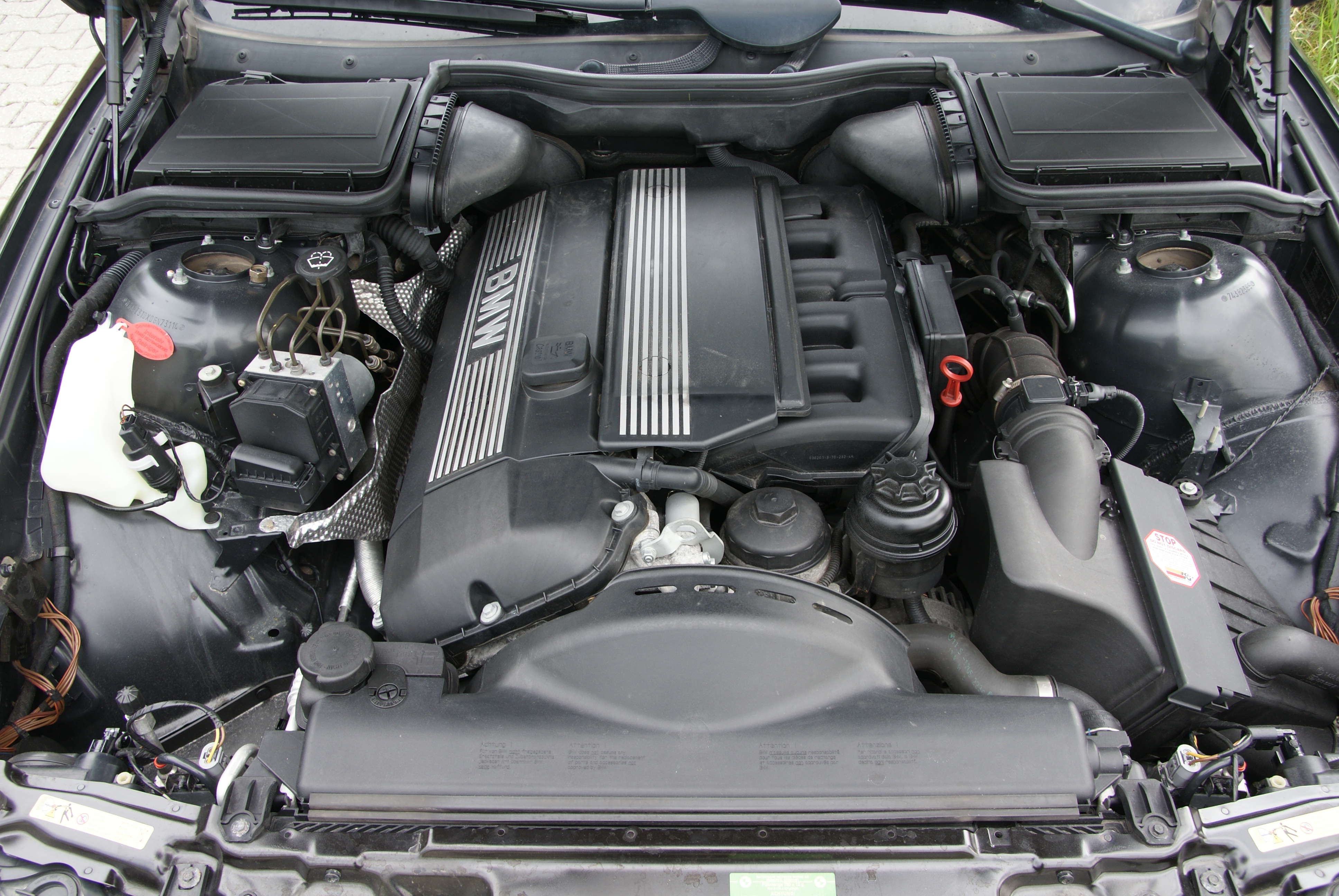
BMW M54B25
Another post as a direct result of my fascination with the E46 3 series.
The BMW M54 is a straight-6 DOHC piston engine which replaced the M52 and was produced from 2000-2006. Compared with its M42 predecessor, the M54 features electronic throttle control. The M54 uses an aluminium block and aluminium cylinder head with cast iron cylinder liners and like the technical updates of the M52, the M54 features variable valve timing for intake and exhaust valves.
The M54B25 is a 2,494 cc (152 cu in) engine with an 84 mm (3.3 in) bore and 75 mm (3.0 in) stroke. Output is 141 kW (189 hp) at 6000 rpm and 245 N-m (181 lb-ft) of torque 3500 rpm.
Displacement: 2,494 cc (152 cu in)
Power: 141 kW (189 hp) @ 6000 rpm
Torque: 245 N-m (181 lb-ft) @ 3500
Redline: 6500
Stroke: 75.0 mm (2.95 in)
Bore: 84 mm (3.3 in)
Compression: 10.5:1
The solution to this problem can be achieved by doing a cooling system refresh.
The BMW M54 is a straight-6 DOHC piston engine which replaced the M52 and was produced from 2000-2006. Compared with its M42 predecessor, the M54 features electronic throttle control. The M54 uses an aluminium block and aluminium cylinder head with cast iron cylinder liners and like the technical updates of the M52, the M54 features variable valve timing for intake and exhaust valves.
The M54B25 is a 2,494 cc (152 cu in) engine with an 84 mm (3.3 in) bore and 75 mm (3.0 in) stroke. Output is 141 kW (189 hp) at 6000 rpm and 245 N-m (181 lb-ft) of torque 3500 rpm.
Displacement: 2,494 cc (152 cu in)
Power: 141 kW (189 hp) @ 6000 rpm
Torque: 245 N-m (181 lb-ft) @ 3500
Redline: 6500
Stroke: 75.0 mm (2.95 in)
Bore: 84 mm (3.3 in)
Compression: 10.5:1
Applications:
- 2001-2002 E36/7 Z3 2.5i
- 2001-2005 E46 325i/325xi
- 2001-2006 E46 325Ci
- 2001-2004 E46 325ti
- 2001-2004 E39 525i
- 2003-2005 E60/E61 525i/525xi
- 2004-2006 E83 X3 2.5i
- 2004-2006 E85 Z4 2.5i
General Information
Reliability
The engine is pretty economic getting decent fuel mileage (approximately 8.8 litres/100 km, Highway, and 16-26 litres/100 km Street), however the most notable issue would be BMW's cooling system which includes a ton of plastic parts which as you can guess, deteriorate overtime do to heat. This leads to catastrophic engine failure if neglected as a whole.
The solution to this problem can be achieved by doing a cooling system refresh.
Wednesday, 13 March 2013
Nissan SR20DET FAQ
*Note - I'm creating this post to aid myself for future reference. Think of it as a cloud database kind of ordeal, but accessible to anyone who needs the information I have archived as well.
The SR20DET is a part of the SR family of engines from Nissan.
It came as a 1.6 L, 1.8 L or 2.0 L straight-4, 4-stroke internal combustion gasoline engine manufactured by Nissan Motors. If features an aluminium head and aluminium block with steel sleeves in selected models and features a DOHC (Dual Overhead Cam) 4-valve design., with variable timing on select models.
| Red Top with sexy custom made exhaust manifold. |
It is a popular engine coming from a variety of Nissan cars, generally the Nissan Silvia (S13, 14, 15) and 180sx (S13).
S13
![]() |
| 180sx Type X (Kouki - 1993-1994) with some Koguchi Power goodies. |
| Rear |
| Silvia (1990-1993), courtesy of Santi at StaticMotion |
S14
| S14 (Kouki 1997-1998) |
S15
| Silvia S15 Spec-R (1999-2002 |
It also came in the Pulsar GTI-R and the Nissan Bluebird (FWD/AWD variants).
| Pulsar GTi-R (All Wheel Drive) |
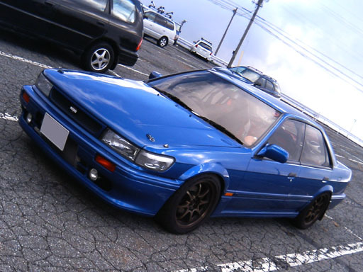
| Nissan Bluebird (Sentra in North America, Front Wheel Drive) |
This engine replaced the CA18DE and CA18DET
| CA18DET, which came standard in a few Nissan vehicles including the first generation 180sx (Zenki) |
Engine Specification (Black Top)
- Type: Water cooled, 4 cycle in-line 4 cylinder
- Valve Mechanism: DOHC (Dual Over Head Cams), 16 Valves (4 valves per cylinder), Chain driven cam sprockets
- Bore x Stroke: 86 mm x 86 mm
- Bore Pitch: 97.0mm
- Block Height: 211.3mm
- Displacement: 1998 cc (rounded to 2.0 litres)
- Compression: 8:5:1
- Throttle Body Bore: 60mm
- Power : 151 kW (205hp) @ 6000rpm
- Torque: 203 lb-ft (275 N-m) @ 4000 rpm
- Turbo: T-25 Garrett
- Stock Boost: 7psi
- Turbine: 62 trim, 53.8 mm (2.1 in), .80, A/R housing
- Compressor - BCI - 1
- 370 cc injectors
- No VCT (Variable Cam Timing) or VVT or VV
| Blacktop SR |
Differences Between Red Top and Black Top SR20 engines
I will define 3 main types of SR20 engines:
S13 Red top SR20: 1991 -1993 model year
S13 Red top SR20: 1994 - 1998 model year
S14, S15 Black top SR20: 1994 - 2001 model years
S13 RED TOP
This engine was only available in S13's manufactured between 1991 and 1994. Its identifying characteristic is that the rocker cover is painted red.
All these engines came out with the following specifications:
- T25G turbo
- 370 cc injectors
- no VCT (variable cam timing)
| S13 Redtop SR |
When comparing this engine to later model S14, S15 SR20's the following characteristics should be noted:
- NO VCT bump on the intake side of the rocker cover
- NO slope on the back of the rocker cover
- LOW mount intake plenum - the intake plenum sits under the intake runners
S13 BLACK TOP
This engine also came out in S13's only. However it was produced in 1994 model S13's. Its mostly seen in 180sx's but may have also appeared in very late model Silvia's.
This engine is almost exactly the same as the S13 Red top SR20.
Aside from the colour of the rocker cover, there are very little changes to the engine itself - the things that were changed possibly include a slightly different head casting (fins on the outside of the head), also in the update model 180sx's (Type X 1996-98) there was a different ECU and some different sensors (water pump sensor).
This motor DOES have the following things:
- T25G turbo
- 370 cc injectors
- No VCT (variable cam timing)
The following characteristics identify an S13 Black top motor:
| S13 Blacktop SR |
- NO VCT bump on intake side of the rocker cover
- NO slope on the back of the rocker cover
- LOW mount intake plenum - the intake plenum sits under the intake runners
S14/S15 BLACK TOP SR20
The S14 and S15 SR20DET has a number of significant differences that need to be pointed out.
This motor was available in all S14 and S15 200sx's & Silvia's from 1994 to end of production in 2001. Confusingly Nissan produced the S13 Black top motor at the same time.
| S15 SR |
The main differences between this motor and the S13 SR20's are:
- Larger T28 turbocharger
- VCT on the inlet cam
- Revised intake design (high mount plenum chamber)
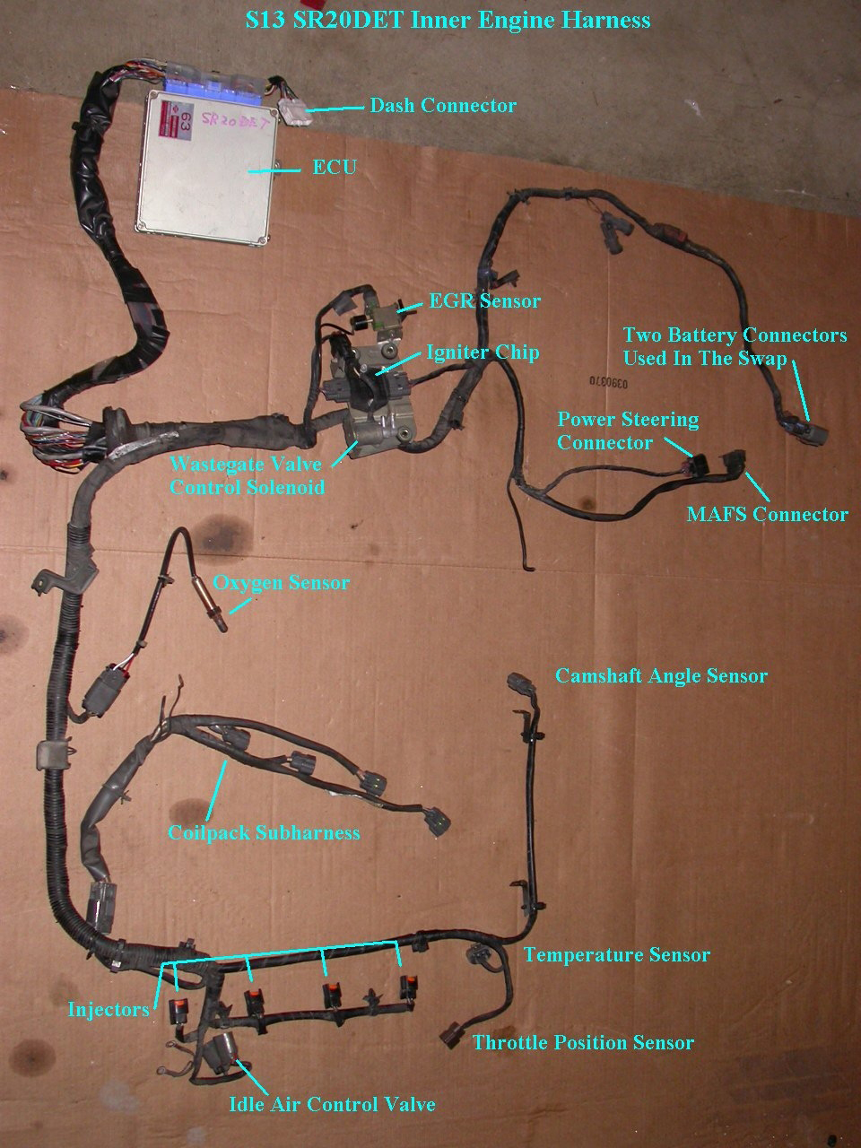
- Different loom and ECU design (not interchangeable with earlier models)
- Different oil filter thread (ryco filter Z445 vs S13 filter which is a Z442)
As mentioned, this motor has a T28 turbocharger, some models have a ball bearing version of this which is subject to a lot of debate.
| T28 Ball Bearing |
The best way to determine if it is a ball bearing turbocharger is by the small Garrett id-plate on the turbo itself:
466541 = Ball Bearing
466543 = Bush Bearing
For the second section the number:
-001 = S14 turbo (no splitter between wastegate and turbine exit)
-002 = S15 turbo (splitter between wastegate and turbine exit)
Later models also have larger 480 cc injectors which are brown in colour. Early S14's had smaller injectors which from memory are 370 cc.
The sloped cam cover, high mount inlet plenum and the bump on the cam cover for the VCT are dead give aways for the S15 Black Top.
COMMON ISSUES
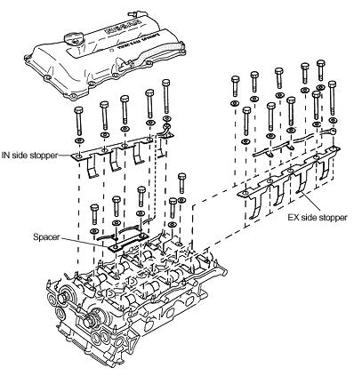
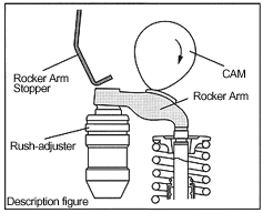
All SR20's suffer a common problematic trait when it comes to snapping rocker arms. Tomei has engineered a "Stopper" that keeps the rocker arms in place at high revs during heavy boost.
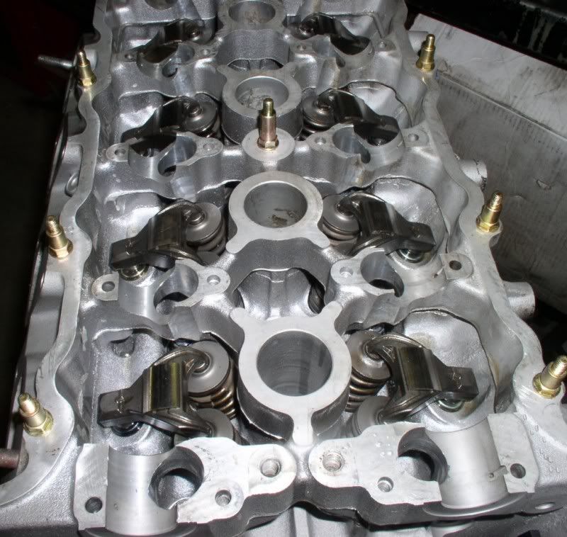
| Rocker Arms in a rebuilt SR head. |
| Tomei Rocker Arm Stoppers |
| Installation schematics |
| Closer look at how the stoppers effectively work |
Now with the S14/S15's, they utilize VVT (Variable Valve Timing) and usually have an issue with the tensioner (rattle comes from the top chain guide under the valve cover). The front cover can wear out and cause slack on the chain thus causing an annoying rattle when in the 2000-3000 rpm range.
Other than that, SR20's are lightweight, suitable alternatives to the KA, CA and RB variation motors.
Subscribe to:
Posts (Atom)